
by Kip Hanson
Turning gargantuan parts? Four cutting tool manufacturers weigh in with recommendations
Not every shop turns parts the size of a redwood tree. Those that do, struggle with super-sized versions of chip control, tool life, part accuracy, and especially horsepower limitations. It’s a niche market, to be sure, but fortunately, a number of cutting tool providers are able to offer the expert advice and metal removal technology needed to assure success in this demanding application.
It’s all about the power
Let’s start with one of the constraints just mentioned. Most “typical” CNC lathes these days have ample horsepower to take whatever depth of cut is needed to get the job done. Not so with machines able to turn parts like wagon wheels, where stalling the spindle on even a relatively light cut is a real possibility, leading to broken inserts and scrapped workpieces.
John Mitchell, general manager for Tungaloy Canada, says tooling for large part turning differs not only in size but also by application. “Tooling selection is often dependent on the machine,” he explains. “Some machines have an abundance of horsepower, where others are limited.”
There’s also part configuration to be concerned with, adds Mitchell, noting that Tungaloy offers three styles of large part turning tools, each suited for specific applications. Its TurnFeed high feed turning option, for example, is able to take a 2.5 mm (0.098 in.) depth of cut and feed rates to match, and should be applied “to large parts with no or only a few shallow shoulders.”
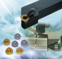 Another option is Tungaloy’s TurnTec family of tangentially mounted turning inserts. These allow for a radial depth of cut up to 15 mm (0.59 in.) and feedrates up to 1.1 mm/rev (0.043 ipr), a tool that Mitchell says offers a very positive cutting geometry and draws less horsepower per cubic inch of metal removed than conventional inserts.
“Occasionally machine shops have lathes where horsepower is not a limitation,” he says. “In these cases, we recommend a very large ISO turning insert such as an SNMG 866. This is a one-inch square insert that can take radial depths of cut up to 19 mm deep (0.750 in.) and feedrates of 1.2 mm/rev (0.048 ipr). Since the insert offers eight cutting edges, it is an economical option, but customers should be aware that a very high horsepower spindle might be required, especially on high strength alloys.”
Monstrous productivity
Another cutting tool provider supporting monster cuts like these is Iscar Canada. Senior product manager Steve Geisel says the company’s Dove IQ Turning line offers a four-sided LOMX tangential style insert that can accommodate cuts up to 35 mm (1.38 in.) per side, but agrees that horsepower is frequently a limitation with such heavy cuts.
“We see a lot of shops trying to produce bigger parts on machines with 35 or 50 horsepower, and a big VTL (vertical turret lathe) might have a little more than that,” he says. “But it’s very rare to see somebody with 100+ horsepower, which for some of these big parts, is exactly what you need.”
One might think the answer is a high positive geometry, to reduce cutting forces. Think again. Large parts such as railway wheels and turbine housings are often not perfectly round to begin with, and may have a tough skin on them. Without a very strong cutting edge, the tool will wear out quickly. The solution is to approach the problem in a way familiar to many machining center operators—use light cuts, taken at very heavy feedrates.
“Depending on the application, we might suggest a WOMG insert using a 2.8-mm depth of cut (0.110 in.) and a feedrate of 3.0 mm/rev (0.118 ipr),” Geisel explains. “Compare that to a traditional CNMG where you often take six times that depth of cut but using a fraction of the feedrate. As with a high feed milling operation, this approach removes metal more quickly but uses far less horsepower.”
 Size (usually) matters
It’s not just the size. Shops supplying parts to the energy or oil and gas industries are frequently faced with super tough metals like Inconel and duplex alloys. Walter Tool‘s product manager Sarang Garud says large part turning happens in various industries. Aircraft turbines, for example, use rings measuring up to 3 m across (10 ft.) made from aluminum or titanium. And there are large electrical shafts maybe 1-1/2 m in diameter (5 ft.) for power generation, as well as large diameter tubes and pump housings, many of them made from steel, stainless steels, or high-temp alloys.
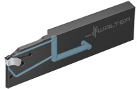
Garud notes that tooling rigidity tends to be an issue with large parts, thanks in part to long tool overhangs to meet the “sheer size of the parts and fixtures.” Walter offers special high rigidity shanks for these applications, as well as special top clamps with multiple coolant holes to flood larger workpieces.
And up-sharp edges aren’t always out of the question, at least not for parts made of aluminum and some aerospace alloys. “Walter offers chip geometries that have a unique combination of strong and sharp for super alloys (NRS) and titaniums (NRT). Also, we have some specialist geometries such as HU6 for heavy roughing applications in steels or cast irons.”
The speeds and feeds listed thus far are on par with what Garud recommends. So, too, are the depths of cut, although he does point out a need for very wide “SX style” parting inserts, which run up to 10 mm in width (0.394 in.) and feedrates of 0.75 mm/rev (0.030 ipr).
Aside from that, the best practices common to all machining operations apply as well to large part turning, although chip control here tends to be a bigger concern than it is on smaller workpieces. “When left uncontrolled, large chips can put the safety of the operator at risk,” he says. “Using the appropriate machining parameters and proper application of cutting fluids not only plays a key role in higher productivity, but also in safety and reduced downtime.”
 Peeling back
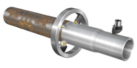
Bar peeling is a heavy turning operation that impacts many in the machining industry, even those who’ve never heard of it. It’s the method used by steel mills to remove the scale and surface cracks that appear on hot-rolled bar and forged blanks after leaving the furnace. It’s also used on axle components for the automobile industry, and thick-walled tubes prior to further processing.
Kevin Burton, product specialist at Sandvik Coromant Co., says the most common materials peeled are carbon steel, spring steel and stainless. “The machining method provides high productivity and low production costs due to the shorter throughput times. Surface quality and dimensional tolerances on peeled parts are also high, which in turn leads to less machining later on.”
Burton offers several bar peeling examples, including one on a 170 mm (6.69 in.) diameter duplex steel shaft, where a WNMX/TNMX dual insert tool was used to remove 5 mm per side (0.197 in.) at a feedrate of 12 mm/rev (0.472 ipr). “We’re also seeing a lot of re-turning of railway wheels, which is often done on underfloor lathes where friction is used to drive the wheel.”
In these cases, Burton says, it might be necessary to take multiple passes in order to achieve in the correct profile and diametral dimensions specified by the wheel manufacturer. Whether single or multiple passes, however, Sandvik Coromant recommends its railway wheel tool system, which consists of holders with replaceable tip seats for tangential inserts.
“This type of insert withstands the stresses which large cutting depths at high temperatures produce,” he says. “When choosing tools and inserts though, it’s important to bear in mind the type of wheel to be turned, the condition of the predominant part of the worn wheel, as well as the available machine power. As with most large turning applications, it’s always best to choose a cutting depth that’s as large as possible in order to achieve short machining times.” SMT