
by Kip Hanson
High speed, high feed, high efficiency machining? Whatever you call it, success requires a balanced approach
It’s about removing large amounts of material quickly. This might mean using high spindle RPM and correspondingly high feed rates. It could be heavy chip loads at lower spindle speeds, but still pushing tools faster than conventional wisdom would suggest. Either way, these and other modern milling methodologies share many similarities, and call for no small investment in software, tooling, and sometimes machinery.
Above all, maximizing your metal removal processes takes a commitment in time–time to learn new processes, time to test and document them, and time to look for additional work thanks to all the newfound capacity on the shop floor.
The right path
Let’s start with the software. Literally dozens of CAM systems exist, all of which claim to have the “right stuff” for fast, productive milling. Mastercam offers Dynamic Milling. SolidCAM has iMachining. HSMWorks promotes Adaptive Clearing. Whatever the technology, choosing the one that’s best for your shop’s needs takes careful research and seemingly endless programming demos. Be patient. You’re going to be married to the software and its supplier for a long time (hopefully), so be sure to make a wise decision.
No matter how you define high speed milling, CAMplete technical support engineer Ivan Mikesic says the goal of any CAM system should be to reduce cycle times while maintaining part accuracy.
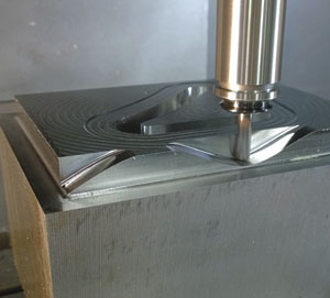
“You want smooth tool motions that avoid sudden changes in direction. This eliminates the need for repeated acceleration and deceleration when tools are forced to maneuver through sharp corners. You want gradual ramping transitions between cutting depths, because if you have to stop, reposition and punch down again, you’re losing time. And you want to keep the tool engaged at all times, while maintaining a constant depth of cutchip load. This will provide the best tool life and productive part throughput overall.”
 Another consideration is the way the toolpath itself is constructed. Where some programmers prefer to define a curved surface using a series of straight lines, or G01 movements, others would rather employ G02 and G03 arcs. Mikesic says a good CAM system will be capable of both. It’s also important that the CAM’s post-processor work seamlessly with the machine controller, and that it can leverage whatever high speed machining functions are available.
“FANUC, Siemens, Heidenhain–each has its own standard high speed machining cycles, but a lot of machine tool manufacturers have developed their own as well,” he says.
“For example, Matsuura typically uses 30i or 31i FANUC controllers, and the generic high speed mode there would be G05, G05.1, or G08 for the AI contour control and Nano-smoothing functions that come with most machines. But Matsuura has written its own G131 high speed function, which offers different modes for roughing, finishing, five axis machining, and other types of milling, but fine tuned for the specific machine tool.
“It’s important to note that CAMplete is not an actual CAM system, but a posting and simulation solution that also supports the high speed machining cycles for all of our machine tool partners. That said, You you need to be sure the whatever CAM system you use supports is able to work with your machine tool’s customthose functions in addition to the control’s generic ones.”
The right machine
Errol Burrell agrees. A machining centre product specialist at Okuma America Corp., he says Okuma’s Super-NURBS and Hi-Cut Pro functions work to more accurately control acceleration and deceleration based on user-definable tolerance bands. It doesn’t matter whether the toolpath is composed of straight or curved lines, the “smoothing” effect will produce highly accurate curved surfaces while speeding up cycle times. This functionality is not a magic bullet, however, and he warns that the CAM system can also play a large factor in high speed machining “by producing uniform point distribution and smart targeted use of the tolerance band.”
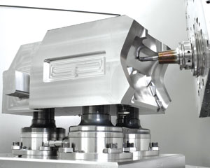
Toolpaths aside, Burrell lists a number of machine tool attributes that are needed for effective high speed machining. The most obvious of these is a fast spindle. Okuma considers anything above 12,000 rpm to be high speed. Depending on the machine size and cutting demands, this would normally be equipped with an HSK-63A or HSK-100A taper. And since high rpm generates commensurately more heat than do lower spindle speeds, Okuma uses a liquid cooled spindle in conjunction with its Thermal Active Stability-Spindle (TAS-S), which monitors and compensates for deviation errors in real time. Similarly, casting and ball screw deviation is managed through Thermal Active Stability-Casting (TAS-C), which works to keep growth to an absolute minimum.
And since high rpm generates commensurately more heat than do lower spindle speeds, a special high horsepower drive unit is used, as well as larger bearings and thermal compensation.
“Thermal stability is critical to predictable high speed machining processes,” says Burrell. “You want a machine with real time thermal monitoring and compensation in all axes, to minimize the growth that comes with any machining operation, but becomes increasingly problematic at higher feeds and speeds. You also need to look at the machine structure. For instance, all of our machining centres are built with simple and balanced shapes. This approach encourages linear, manageable growth, and is a main tenant of our principles of design.”
Whatever the machine brand and its technology, high speed machining produces tremendous axial inertia, making it critical that shops anchor their machines to the floor, preferably to an isolated concrete foundation. And thermal compensation notwithstanding, if your shop is hot in the summer and cold in the winter months, it’s time to turn a blind eye to the energy bill and turn on the HVAC. This adage is true for anyone hoping to maximize part accuracy, but especially so for those hoping to succeed on the cutting edge.
The right holder
Not everyone can afford a new machine, though, and must make do with whatever outdated or commodity machine is currently on the production floor. That doesn’t mean they should give up on high speed machining, however. In many ways, the smooth movements, consistent cutter engagement, and light depths of radial cut common with high speed toolpaths are well suited to less capable machine tools.
Still, even if that old dinosaur can only hit 8,000 rpm or so, balanced, high quality toolholders are a must, particularly with the steep taper, non-HSK spindles common on these machines.
Drew Strauchen, vice president for marketing and business development at Haimer USA, offers the following consideration, aimed at those that assume one brand of toolholder is much the same as any other. “Balance is obviously a big part of the high speed machining equation, but taper accuracy and rigidity are just as important,” he says.
 “Unfortunately, many companies that advertise the AT3 quality tolerance for 40 and 50 taper toolholders–the de facto industry standard–are actually unable to meet that standard. But without it, you will never achieve the 90 to 95 per cent spindle engagement needed for optimized high performance machining.”
Strauchen recommends verifying toolholder quality with special air or physical contact gauges, or better yet, the shop’s CMM. The machine spindle should likewise be routinely inspected for wear by a certified technician. Assuming everything is up to snuff, Strauchen further recommends balancing the holder as a complete assembly, retention knob included.
“There are a lot of misnomers about balance, and this is one of them,” he says. “We definitely suggest a piloted pull stud be used, as this locates on a precision-ground journal and face rather than on the threads. This is standard with many BT style holders but not so with CAT, so you have to look for and invest in that option. And always balance the entire tool assembly, even with HSK holders. In most high speed machining environments, a single plane balancing to G2.5 at the machine’s maximum rpm is more than adequate, but on very long tools or non-concentric form tools, at extreme spindle speeds, balancing in two planes might be necessary.”
The right cutting tool
Like most toolholding experts, Strauchen says that shrink fit is often the first choice for high speed machining applications, but adds that high feed operations with heavy side loads like full radial engagement trochoidal milling might require an anti-pullout system like Safe-Lock to ensure tool security.
Of course, even the best milling chuck is worthless without an equally capable cutting tool.
Ron Field, vice president of cutting tool provider Millstar, a division of Cole Tooling Systems, says that most cutters today fall into one of two categories: indexable tools able to take high feed rates at relatively low axial (Z -axis) engagement, and solid carbide end mills designed for trochoidal, full length cuts.
In either case, cutting forces are lower than with traditional machining approaches, but Field notes that button style indexable high feed cutters do a better job of directing cutting forces up into the spindle, right where you want them.
“We’ve long had high feed cutting tools available in both indexable and solid carbide, but recently introduced our Quad Force line,” he says. “This is a hybrid, variable helix, variable pitch carbide end mill that’s able to do trochoidal machining, side and slot milling, plunging, and pretty much whatever you throw at it. In a high speed or high feed milling application, it eliminates much of the need for multiple tools to perform different operations.”
The right solution
High speed, high feed machining covers the entire trilogy of aerospace, medical, and die mould machining, and Field can offer plenty in terms of machining advice for each, including what cutting tool works best for a given application and how to apply it. One thing that he and the others interviewed for this article wholeheartedly agree on is that high performance milling of any kind is a complete package.
“The cutting tools and toolholders, the machine, the cam system–it all has to work together or it doesn’t work nearly as well, if at all,” he says. “But once you learn the technology and begin to apply it, the benefits are incredible. We worked with one shop recently that took an eight hour cycle time and brought it down to 55 minutes. And that was on an older machine. I’d say that, as a rule, companies can easily see a ten-fold increase in productivity, with better tool life and less wear and tear on the machine tool. There’s simply no reason not to do it.” SMT