
by Amada Weld Tech
The benefits of closed-loop control for the resistance welding process
Closed-loop resistance welding power supplies use current and voltage feedback sensors to control the energy delivered to the parts. Closed-loop technologies provide many benefits for the resistance welding process including:
- Controlled Heating Rates
- Feedback Mode Options
- Repeatable Weld Heat
- Weld Monitoring Capabilities
- Continuous Heating
- Process Tools
Taking full advantage of these benefits requires a good understanding of resistance welding principles.
CONTROLLED HEATING RATES: At the beginning of a resistance weld there is high electrical resistance at the electrode-to-part and part-to-part contact areas (Figure 1). If too much energy is applied before the electrodes have a chance to seat properly, these contact areas can overheat, resulting in expulsion, electrode sticking, and weak welds (Figure 2). Closed-loop power supplies allow a very precise upslope to be programmed at the beginning of the weld pulse. This upslope of current, voltage, or power helps to reduce the initial contact resistance and focus weld heat into the parts. The length of the upslope period can be programmed to suit the application. A long upslope is recommended for very hard or resistive parts.
REPEATABLE WELD HEAT: In the first few milliseconds of a resistance weld, the work piece resistance drops rapidly as the electrodes and parts seat together. During the weld, resistance values shift as contact resistance decreases and bulk resistance increases. Closed-loop power supplies can respond to these changes every 10-250 microseconds, depending on the power supply model, allowing closed-loop power supplies to produce more consistent welds, especially for difficult to weld parts.
CONTINUOUS HEATING: Linear DC and High Frequency Inverter power supplies can supply DC welding energy for extended time periods with no off time. This is in contrast to AC power supplies which turn the power on and off every half cycle. Small parts often require short welding times and a high degree of control in order to achieve welding consistency. DC welding energy results in smoother temperature curves and shorter weld times, leading to less weld splash, less chance of voids, extended electrode life, and more part ductility.
FEEDBACK MODES: As previously stated, closed-loop power supplies use voltage and current sensors to control the energy delivered to the parts. The energy can be delivered in the form of Constant Current, Constant Voltage, or Constant Power. In the Constant Current mode, the power supply will deliver the programmed current regardless of work piece resistance changes. Constant Current can compensate for slight changes in part thickness without affecting weld quality. It is best suited for welding flat parts where the part-to-part and electrode-to-part contact is controlled and consistent. The Constant Voltage mode controls the voltage across the work piece during welding, which can help to compensate for part misplacement and force problems. It automatically reduces weld splash, which is often associated with welding non-flat parts and wires. The Constant Power mode precisely varies the weld current and voltage to supply consistent weld energy to the parts. It is especially useful for breaking through surface oxides and plating. Constant Power should be considered for automated applications where part or electrode surface conditions can vary over time.
WELD MONITORING: The voltage and current feedback sensors used for closed-loop control are also used to provide process monitoring data. Peak and average values of weld current, weld voltage, weld power, and work piece resistance can be used for process development and statistical process control. Graphic waveform traces provide simple, dynamic weld information for process analysis and understanding. Upper and lower reject limits can signal operators and automation via programmable relay outputs.
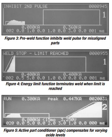 PROCESS TOOLS: Advanced monitoring features can be used to reduce or eliminate inconsistent welds caused by process and material problems. The Pre-Weld function and Energy Limit function are used to detect missing or misaligned parts. The Active Part Conditioner (APC) feature is designed to help cope with varying oxide levels on part surfaces. The Pre-Weld function uses a short, low current pulse to measure work piece resistance prior to the application of the welding pulse. An upper voltage limit on the constant current pulse is used to detect misaligned parts. With constant current applied, the voltage across the work pieces will be very consistent if the parts are aligned consistently from weld to weld. If the parts are misaligned, the work piece resistance will be high, causing a high voltage, out of limits condition. When misaligned parts are detected, the weld pulse is inhibited (Figure 3), thereby avoiding blown welds and damaged electrodes.
The Energy Limit function uses limits to detect either missing or misaligned parts. With this feature, the weld energy is terminated when a programmed current, voltage, or power limit is reached (Figure 4). For example, in a constant voltage weld, the current will spike if a part is missing. An upper current limit is used to detect the missing part. A lower current limit is used in the same fashion to detect misaligned parts.
Bringing each part to the same resistance level prior to welding can help to minimize weld splash and increase process yields. The Active Part Conditioner (APC) feature uses a constant power first pulse to break through surface oxides. When the constant power first pulse is applied to the parts, the voltage starts out high, since surface oxides restrict current flow. This high voltage breaks down the oxide layer, allowing more current to flow through the parts as resistance decreases. When the current level reaches a preset limit, the first pulse is stopped, and the second pulse is allowed to fire (Figure 5). The APC feature automatically adjusts the first pulse time based on the amount of oxides present on the part surfaces.
SUMMARY: Closed-loop power supplies offer many benefits to the resistance welding process. The ability to accurately control weld energy is a key factor in overcoming the problems associated with the rapid changes in resistance during the weld. Small parts, which require shorter welding times, benefit from constant heating and feedback mode options. Weld monitoring features and process tools facilitate the implementation of successful process control programs, which are designed to meet demanding production and quality requirements. For resistance welding, closed-loop is clearly the technology of choice today and in the future. SMT