
by Kip Hanson
New grooving and parting tool geometries make easy work of an otherwise arduous task, provided the right cutting parameters are applied
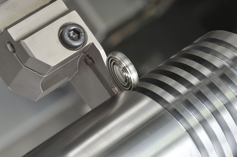
Back in the screw machine days, grooving was a simple task. Grind a brazed carbide tool to whatever width groove the print called for, give the edges a quick hone and get plunging. Cutoff was even easier. Just sharpen the edge of a high speed steel T-blade, mount it in a special holder, and crank up the hydraulic pressure until the thing started cutting. The problem was, none of it worked very well. Chip control was done by snagging the resultant bird’s nest of curled up metal with a hook. Sometimes the braze would break loose and the painstakingly ground bit would end up in the chip tray, or the cutoff blade would snap due to overly aggressive feedrates. Grooving simply wasn’t much fun.
Doubling down
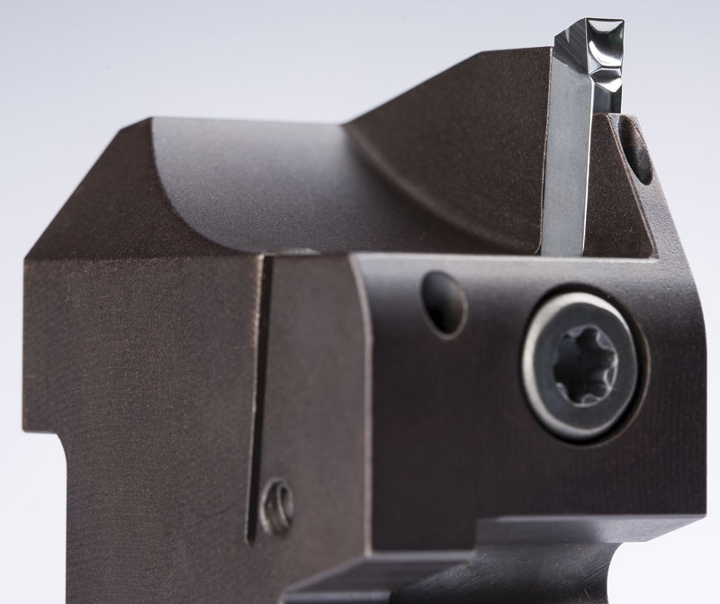
Brazed tools have largely gone the way of retired machinists, replaced by a bewildering variety of grooving and parting inserts. Most do an excellent job of chip control and provide far greater tool life than anything we might have imagined in the pre-CNC days. One of the pioneers in this area is Iscar Tools Inc., Oakville, ON. Senior product manager Steve Geisel says the original single-sided Self-Grip style inserts introduced in 1978 are still available, but are slowly being replaced by better cutting tool technology, including tools that can groove, turn, and part with the same holder.
“There will always be a place for single-sided inserts,” he says. “For very deep grooves, and in shops that would rather not keep track of the remaining uses on a multiple cutting edge insert, or worry about losing the entire insert when an edge breaks—these are good applications. But it’s also important to recognize that single-sided inserts present the highest cost per edge, perhaps 30 per cent more expensive than our double-sided Do-Grip or Heli-Grip, and easily 50 per cent than that of our five-sided Penta-style inserts.”
Geisel offers a number of general recommendations. Due to limited depth, multi-edge inserts are best used on small parts and shallow grooves, particularly in high wear applications where tooling costs are a concern. Grooves wider than they are deep should be turn-grooved rather than plunged, using an insert designed for such work. Take a depth of cut no greater than 3/4 of the insert width, lower the spindle speed perhaps 10 to 20 per cent and substantially increase the feedrate—between 0.51 to 0.76 mm/rev (0.020 to 0.030 ipr) is possible with many materials. And if you’re not getting the desired performance, send an email to your rep or pick up the phone. Most cutting tool manufacturers have extensive grade, geometry, and chip breaker choices, and knowledgeable people ready to help. There’s no reason to settle for less than stellar performance.
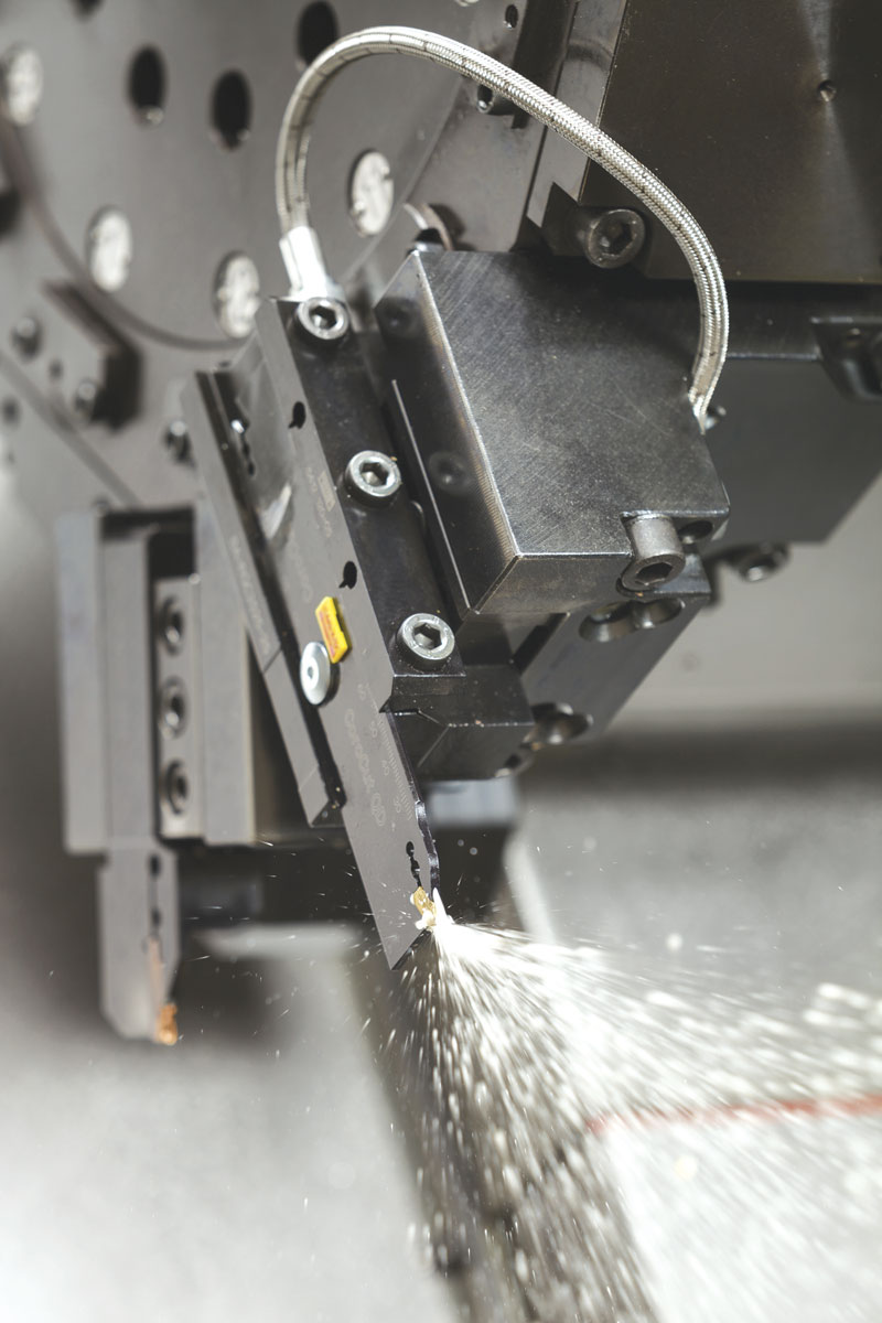
 One often overlooked grooving game changer is high pressure coolant (HPC). Geisel says HPC provides huge benefits in tool life and productivity, but estimates less than five per cent of Canadian shops use it. “Even at standard pressures, through-the-tool coolant is a big help, but going to 69 bar (1000 psi) makes a night and day difference. Some of our customers are seeing three to five times improvement in high-temp alloys. Because of this, we’re making all our grooving products capable of 345 bar (5000 psi), something Iscar calls Jet-Cut, in anticipation of ChipBlaster and other HPC system manufacturers moving towards higher pressures.”
Hard lessons
Dan LaFauce, supervisor for Sumitomo Electric Carbide Inc.’s tool engineering centre (A-TEC) in New Berlin, WI, says the most common problems with grooving and parting can be solved through proper insert selection for the given material, and using the right speeds and feeds. “We do a lot of training classes at the ATEC, teaching people how to use tooling correctly. A lot of customers aren’t familiar with the new cutting tool technology that’s available today, so we offer four different levels of training where they learn how to read chip wear, what to listen for during the cut, how inserts are designed and what geometry works best, that sort of thing. It’s a great class.”
When not educating machinists, LaFauce is often busy doing test cuts with customer parts and material. He says it’s very important to prove out cutting processes before going into production, something that’s especially true with difficult materials such as titanium and hardened steel. “People don’t always have time to test properly, so we’re happy to dial in the correct tooling and cutting parameters for them.”
One example of this is a test cut LaFauce had scheduled for later that week, a grooving application using CBN. “Most grooving is tricky, but especially when you get up in the 50 to 65 Rc range,” he says. “We did another test recently with some 88 per cent tungsten material, hardened to 72 Rc, where we brazed a polycrystalline diamond (PCD) tip onto one of our GND groove/turn inserts. It was pretty difficult stuff, but we got it working. What’s important is the procedure you use for fine tuning. There are so many variables: work holding, type of material, depth and width of cut. Once you achieve a stable process, you should never change more than one variable at a time, so if something does go wrong, or if you manage to improve the process, you know exactly how you did it.”
 Bubble up
Ironically, one of the easiest materials to machine is often the most difficult in terms of chip control. Jason Farthing, technical sales and marketing for Horn USA Inc., Franklin, TN, says the company’s newly developed WA-style S100 single-sided and S224 double-sided inserts have a polished top surface, positive geometry, and sharp edges for efficient aluminum machining. “It’s really tough to break the chip on aluminum. More often than not you end up with one big, long string. The WA geometry forces the chip to fold up on itself and break instead of bird-nesting or shooting all over the machine.”
Farthing agrees on the importance of coolant through the tool, but says it has to be done correctly. Horn’s version includes a coolant hole inside the chip groove and directly behind the cutting edge. This prevents material from plugging the orifice, an event that can lead to catastrophic results. He also recommends cutting fluid pressure of no less than 50 bar (720 psi) whenever possible. “The more the merrier, but it takes at least that amount to overcome the steam bubbles that form during cutting,” Farthing says. “This also helps to break the chip more efficiently. HPC is the only way to take full advantage of the newer grooving geometries, and once shops make the move, they never regret it.”
 Parting ways
Kevin Burton, parting and grooving specialist for Sandvik Coromant Canada Inc., offers similar advice on parting applications, which due to insufficient spindle rpm as the tool approaches centreline often results in chipped or broken tools. He recommends reducing feedrate by up to 75 per cent during the last 2 mm of the cut (0.08 in.) and, on stainless steel and alloys high in nickel, turning off the cutting fluid. “Despite all the good advice that promotes HPC, running dry that last little bit helps reduce the built up edge (BUE) that comes with these materials,” he says. “It’s also critical that tools be on centreline, and have as short an overhang as possible. If all else fails, some shops will actually stop the tool a bit short of centre and pop the part off by hand.”
Not all grooving is in the X axis, however. Burton points to a recent example with an automotive customer machining large face grooves in forged S35C steel. As with many grooving applications, the chips were long and stringy, and frequently wrapped around the toolholder and chuck, forcing frequent stops to clean the work area. Worse, scratches in the finished surface often led to scrapped workpieces. Sandvik Coromant application specialists replaced the existing cutting tools with CoroCut 1-2 face grooving tools, moved from flood coolant to 80 bar (1160 psi) through-the-tool HPC, and reprogrammed the machine to use a pecking toolpath. The result was greatly improved chip control and a 30 to 50 per cent increase in feedrate and spindle rpm, giving the customer a 65 per cent productivity improvement and no scrap.
“This is a great example of what happens when customers come to us for help,” says Burton. “Not only did we help with this particular application, but they were able to take their newfound knowledge and apply it throughout the shop.” SMT