
by Kip Hanson
Light cuts and high feedrates spell improved rough milling operations
Conventional wisdom has long advised shops to grab the biggest end mill the machine can handle and start hogging. Full width cutter engagement, spindle load meters pegged to the redline, the growl of overtaxed spindle motors and axis drives–if this sounds like a typical roughing operation at your shop, then listen up: milling like a ballerina is faster than ploughing like an ox.
Laying down for the job
High feed milling, or HFM, removes metal by using light radial depths of cut, moderate cutting speeds, and extremely high feedrates. Brian MacNeil, milling products and application specialist at Sandvik Coromant in Canada, says the secret is the chip thinning effect achieved when small entering angles are used. This can be achieved with button style end mills that use round inserts, although Sandvik Coromant and others have developed cutters specially designed for HFM, with very shallow insert orientation. “With a square shoulder, 90° tool, cutting forces are radial,” says MacNeil. “As you lay down the insert from 90 to 19, 15, or even 10°, your cutting forces become axial, and are directed back towards the spindle. This serves to thin the chip, and allows for substantially higher feedrates. About the only time this is a disadvantage is if you are cutting a thin floor, where deflection can become a problem.”
MacNeil says HFM is common across all materials and industries today. Because it reduces heat in the cutting process and directs cutting forces upwards, it is suitable for even light duty machine tools. The only caveat is that you do not exceed the machine’s ability to move quickly in smaller areas. This can lead to damaged tools. However, most modern CNC machine tools have the processing power and dynamic motion capability to keep up with the demands of HFM.
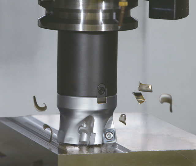 On very large machines working in small areas, MacNeil suggests button cutters be used, as these offer a good compromise between depth of cut (DOC) and feedrates. For general purpose HFM work, he recommends the CoroMill 745, which uses a large, thick insert placed deep into the cutter body to minimize movement, or the CoroMill 415, Sandvik Coromant’s new small diameter high feed cutter launched in 2016 and designed with “new steel, new screws and an I-Lock tip seat to better secure the insert.” Whatever cutter is used, MacNeil says, be aware that the greater the insert angle, the lower the amount of chip thinning, thus forcing commensurately lower feedrates to be used. Conversely, as the angle becomes shallower, more chip thinning occurs and feedrates can be increased accordingly.
“Another consideration is cooling,” he says. “You can generally run dry in steel, but through-spindle compressed air is a big help for removing chips from the cutting zone. And with heat resistant super alloys and materials high in nickel, high pressure coolant is recommended for removing chips and reducing heat. Always choose a tool diameter and geometry that fits your machine’s torque curve and spindle size, and remember that a bigger tool is not always a more productive tool.”
Turn out the lights
Paul Rice agrees. An applications engineer at Kyocera Precision Tools, he says HFM works well in a variety of materials, “including but not limited to carbon steels, alloy steels, stainless steels, heat resistant alloys, and titanium.” Cutting conditions vary depending on the type of material, Rice says–for example, slower feeds and speeds should be used when machining heat resistant alloys, but can be greatly increased when machining low carbon steels.
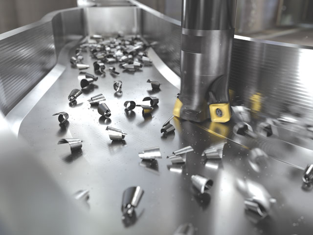
Rice defines HFM as feeding a milling cutter at rates greater than 2,500 mm/min (100 ipm). He offers an example where a 63 mm (2.5 in.) diameter five-flute Kyocera MFH Raptor series face mill was used to cut carbon steel at 180 m/min (600 sfm) with a 1.8 mm DOC (0.070 in.) and 1.8 mm feed per tooth. This equates to 917 rpm and a feedrate of 8,153 mm/min (321 ipm). No cutting fluid was needed, only an air blast to clear chips out of the way.
 This is made possible by HFM’s ability to reduce cutting forces drastically and spikes in spindle loads when entering and exiting tool paths, Rice explains. “In theory, the more cutting edges you provide, the faster you can feed the cutter. However, the body of the cutter can be weakened and fail if too many cutting edges or flutes are present.” That’s why it’s important for cutting tool manufacturers to stress test their milling cutters, he says, providing the best ratio between the number of cutting edges and a tool’s cutting diameter.
Rice notes that tool life is a major consideration with HFM, but consistency is also very important. “That’s especially true for customers that perform machining operations with no one present at the machine. With the extended tool life and consistency offered by Kyocera’s line of HFM cutters and Mega Coat grades, lights-out machining has never been more practical.”
A few tips
Tim Aydt, product manager indexable milling for Seco Tools LLC, offers a number of tips for HFM. For example, always use the most rigid, capable machine possible. Select the right grade for the job to avoid premature insert failure, and maximize time between tool changes. Optimize cutter paths to minimize sudden changes in direction, and avoid burying tools in corners. Maintain consistent cutter engagement wherever possible, thus reducing shock to the cutter and machine tool. And look to trigon-style or similar geometry inserts, as these offer the lowest lead angles possible, minimizing chip thickness and providing the highest feedrate.
Aydt says Seco’s new line of HFM cutters allow parts to be machined up to 10 times faster compared to traditional methods. And its Jabro and Niagara solid end mills and Minimaster Plus replaceable tip cutters are especially well-suited to mould and die, aerospace, and other industries, where high feed milling is used to remove large amounts of tough materials quickly. He also recommends a product released in the fall of 2016, the High Feed 6 (HF6) double-sided trigon shell mill, which Aydt says is effective at high feed face milling, slotting, and contouring of difficult materials. “For those willing to take the leap, the benefits of high feed milling can significantly outweigh its potential challenges,” he says. “The process offers amazing productivity, nearly triple the metal removal rate of conventional methods, and increased tool life.” SMT