
by Mary Scianna
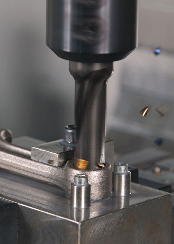
Cutting tool design is crucial for effective chip management
It is the eternal problem every manufacturer faces when machining metal alloys; managing chips during cutting so they won’t adversely affect cut quality or cutting tool life.
While chip control is critical for any cutting processes, for the purposes of this article, we ask suppliers about chip management in milling and drilling applications.
There are three main factors that affect chip control: cutting conditions (feed rates, the depth of cut and the cutting speed); the work material (the type and hardness of an alloy and heat treatment); and tool geometry (cutting angles).
For instance with work material, different alloys will yield different lengths and thicknesses of chips. Mild steel chips, for example, are thicker than those of hard steel, but hard steel chips are liable to curl more than those of mild steel, says John Mitchell, general manager of Tungaloy Canada, Brantford, ON.
It’s one reason why Bill Fiorenza, die and mould product manager for Ingersoll Cutting Tools, Rockford, IL, is a big advocate of education for cutting tools. “When customers are looking for chip management or require extended reach applications, I usually suggest a particular insert in our milling line to begin with and the reason I do this is because you have to learn how a cutter performs since all cutter geometries perform differently in milling applications.”
Changing shapes
The multiple tooling geometries available today are all designed to cut materials more efficiently and to evacuate chips more effectively from the cutting zone.
These tooling geometries include complex surface profiles (round, oval or angled edges found on inserts) with multiple cutting edges. The sharpness of these cutting edges will determine the thinness or thickness of a chip or the formation of the chip. For instance, sharper geometries in milling inserts are typically best for ductile materials because they help to lower the temperature in the cut and reduce work hardening.
Selecting the right geometry is dependent, in part, on the material you’re cutting, says Tim Aydt, product manager, indexable milling tools, Seco Tools Inc., Troy, MI.
“When you consider different materials, each require different geometry forms for different types of operations you’re performing in a machine.”
 So it makes sense that you use the right geometry for the right material, says Cheryl Kincanon, an applications engineer for drilling products with OSG.
By way of example, Seco’s Tim Aydt cites Seco’s Double Octomill series of indexable carbide inserts designed with 16 edges. A recent addition to the family is the MS2050 grade for titanium machining. It’s available in a variety of positive geometries for square shoulder milling, face milling, copy milling and high feed milling.
Kincanon cites a new OSG drill, the WDO-SUS, as an example of the role geometry plays in chip management.
“The new flute geometry has a relief, allowing stainless steel or titanium material to curl a lot faster and break off into smaller chips, for better flow through the flute.”
The new drill also features a larger-than-normal coolant hole, allowing for 33 per cent more coolant volume than in standard drills, says Kincanon, providing improved chip evacuation.
Increasingly, flute geometries are being incorporated into many cutting tools because of the geometry’s ability to curl and cut chips more effectively for better chip evacuation. “The design of a flute dictates how well the chip curls,” says Alyssa Walther, an applications engineer for milling products at OSG. “Chip curl is important because you don’t want chips to stick to the tool. With a flute form, you achieve a smoother curl, generate less heat and throw the chips out faster,” she explains, referring to OSG’s new end mill design for its UVX-NI, designed for milling nickel based alloys.
Flute design is an important factor in drills when it comes to chip control and evacuation, says Randy McEachern, product and application specialist with Sandvik Coromant, for holemaking and tooling systems, based in Mississauga, ON.
“If the chip coming off the cutting edge is bigger than the shape of the flute, then that chip is going to jam and negatively affect the cutting process. What I recommend to customers is to drill two holes, collect the chips and then place them by the flute of the drill the way the chip would come off the cutting application. You can either take the drill off the machine or use a spare one. If the chip was the correct size for the application, what you would see with a CoroDrill 870, an exchangeable tip drill, is that the chip formation would be the same shape as the flute formation; it would fit like a glove. So the chip would slide up and out of the flute and evacuate effectively. If chips are smaller than the flute, you won’t have any problems, but when the chip is bigger than the flute, you’re going to get that jamming of chips.”
For replaceable tip/steel body type drills, Ingersoll’s Gold-Twist drill line features “several unique cutting edge geometries (P, M and K) that are specific to the ISO material standards for improved tool life,” says Susan Valenti, product manager for holemaking at Ingersoll. “Our new flat bottom geometry creates a true flat bottom without sacrificing chip control.”
Chip splitting technology
Suppliers began to focus more on insert design ten to 12 years ago, says Ingersoll’s Fiorenza. “Today, you’re seeing, for instance, button cutters [for milling] with inserts that have positive rake face geometries that incorporate serrations that produce very small chips and manage cutting forces very well in applications that require long length-to-diameter ratios.”
Chip splitter inserts (chip breakers and serrations) offer end users several benefits, says Fiorenza. Smaller chips are more easily evacuated from the work area and milling cutting forces are reduced, “especially in long reach applications such as long stick outs, length-to-distance ratios.” An important benefit from this technology is that it helps to reduce heat generated during the cutting process, which in turn extends tool life.
Chip splitters can compromise material removal rates, warns Fiorenza. “Sometimes when you introduce chip splitters you may need to revise operating parameters (feeds and speeds) because you can’t get as aggressive with feed rates, but that’s not always the case. IngersollTV has a video of a Form Master R button cutter utilizing a serrated style insert cutting at 232 imp, which matches the feed rate of non-serrated technologies.”
Tool angles
Rake and lead angles or drill point angles in drilling, help manage chips during cutting.
Positive and negative rake angles affect cutting forces and help guide chip flow. One of the issues manufacturers face when selecting cutting tools is that sometimes there’s a tradeoff in benefits. For instance, positive rake angles help form continuous chips in ductile materials and can help prevent built-up edge, but they also typically make a tool more pointed and sharper, which reduces the tool’s strength, explain suppliers. Negative rake angles make a tool more blunt and increase the strength of the cutting edge and increase cutting forces, but that leads to increased friction and higher temperatures, which will increase tool wear.
The same tradeoff holds true of lead angles, says Seco’s Aydt.
“If you’re taking a 3 mm depth of cut with a tool with a 90° lead angle, 3 mm of that edge is in the cut. But if you take a 45° lead angle at the same depth of cut, more of the insert is engaged in the cut at this angle than the 90° one. So you have thinned out the chip with the 45° lead angle so the average chip thickness starts to go down, which means you can increase the feed rate.”
Indeed, this is the basic principle behind high feed milling, says Tungaloy’s John Mitchell, who commented on lead angles in a Cutting Tools Tech Tips in the August 2014 issue.
“Due to the lead angle, a typical high feed milling cutter will produce an average chip thickness of less than 20 per cent of the programmed chip per tooth, calling for extremely high feed rates. The cutting force is directed down into the part and directly up into the spindle, extending machine tool life.”
In holemaking applications, drill point angles, similar to lead angles in milling and turning processes, play an important role in chip management, says Sandvik Coromant’s Randy McEachern.
“There are four design features that will give you good chip control and good evacuation with any material: cutting edge geometry, drill point angle, helix angle and the depth of the flute.”
Listen to you chips
To understand how your cutting process will impact chip control and evacuation, manufacturers can run visual simulations to estimate chip size and shape and then select the appropriate tool. But software isn’t enough, says Sandvik Coromant’s Randy McEachern.
“You need to listen to the sounds your machine is making, especially in drilling applications. You can’t see what’s going on in that hole and with today’s high pressure coolants, you can’t see anything. So you need to listen to the chips. If the chips are hitting the door of the machine, it’s a good indicator that chip evacuation is working. But if you hear a low rumbling sound, it’s can be an indication of chips not evacuating properly.” SMT